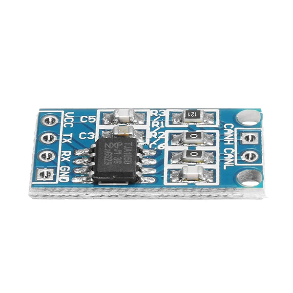
Bus Driver Speed Module
Serial Peripheral Interface (SPI)SPI is the “Serial Peripheral Interface”, widely used with embeddedsystems because it is a simple and efficient interface: basically amultiplexed shift register. Its three signal wires hold a clock (SCK,often in the range of 1-20 MHz), a “Master Out, Slave In” (MOSI) dataline, and a “Master In, Slave Out” (MISO) data line. SPI is a fullduplex protocol; for each bit shifted out the MOSI line (one per clock)another is shifted in on the MISO line. Those bits are assembled intowords of various sizes on the way to and from system memory. Anadditional chipselect line is usually active-low (nCS); four signals arenormally used for each peripheral, plus sometimes an interrupt.The SPI bus facilities listed here provide a generalized interface todeclare SPI busses and devices, manage them according to the standardLinux driver model, and perform input/output operations.
At this time,only “master” side interfaces are supported, where Linux talks to SPIperipherals and does not implement such a peripheral itself. (Interfacesto support implementing SPI slaves would necessarily look different.)The programming interface is structured around two kinds of driver, andtwo kinds of device. A “Controller Driver” abstracts the controllerhardware, which may be as simple as a set of GPIO pins or as complex asa pair of FIFOs connected to dual DMA engines on the other side of theSPI shift register (maximizing throughput).
Such drivers bridge betweenwhatever bus they sit on (often the platform bus) and SPI, and exposethe SPI side of their device as a. SPI devices are children of that master,represented as a andmanufactured from descriptors which are usually provided byboard-specific initialization code. A is called a “Protocol Driver”, and is bound to aspidevice using normal driver model calls.The I/O model is a set of queued messages. Protocol drivers submit oneor more objects,which are processed and completed asynchronously.
(There are synchronouswrappers, however.) Messages are built from one or moreobjects, each ofwhich wraps a full duplex SPI transfer. Community custody program. A variety of protocol tweakingoptions are needed, because different chips adopt very differentpolicies for how they use the bits transferred with SPI.struct spistatisticsstatistics for spi transfersDefinition. The driver is finished with this transfer it mustcall so the subsystemcan issue the next transfer.

Ft601 Drivers
Note: transferone andtransferonemessage are mutually exclusive; when bothare set, the generic subsystem does not call yourtransferone callback. Handleerr the subsystem calls the driver to handle an error that occursin the generic implementation of transferonemessage. Csgpios Array of GPIOs to use as chip select lines; one per CSnumber. Any individual value may be -ENOENT for CS lines thatare not GPIOs (driven by the SPI controller itself). Statistics statistics for the spimaster dmatx DMA transmit channel dmarx DMA receive channel dummyrx dummy receive buffer for full-duplex devices dummytx dummy transmit buffer for full-duplex devices fwtranslatecs If the boot firmware uses different numbering schemewhat Linux expects, this optional hook can be used to translatebetween the two.DescriptionEach SPI master controller can communicate with one or more spidevicechildren. These make a small bus, sharing MOSI, MISO and SCK signalsbut not chip select signals. Each device may be configured to use adifferent clock rate, since those shared signals are ignored unlessthe chip is selected.The driver for an SPI controller manages access to those devices througha queue of spimessage transactions, copying data between CPU memory andan SPI slave device.
For each such message it queues, it calls themessage’s completion function when the transaction completes.struct spiresspi resource management structureDefinition.
The USB-CANmodul1, is a small-sized and very cost-effective CAN-bus interface solution for connecting the CAN-bus to the PC via USB. CAN messages are tunneled transparently - thereby the module can support all kind of higher-layer CAN-based protocols, such as CANopen, SDS, DeviceNet or J1939. Its fast yet low-power 32-bit CPU core with integrated message buffers ensures reliable communication even at high busload. PhysicalSize (LxWxH)78 x 45 x 18mmWeightapprox.